Fokker Eindekker Build – Autumn 2014
Part One
I have long held the wish to build a “dawn patrol” WW1 type model aircraft, and thought that a monoplane would be where to start. I spotted a Fokker Eindekker plan on EBay – a David Boddington Aero modeller freebie 1982 vintage, bought it at auction for £4.00 odd, and had it enlarged to approximately 1/6th scale at the local printers – up scaling brought the wingspan to 57”, which is a much more manageable flying size and weight than the DB 1/8th scale published in the magazine.
The attraction of the Eindekker is exactly that – only one wing! Having looked at numerous biplanes and the various plans available, I doubted my ability to construct the wings and associated struts accurately, and to be able to assemble the entire airframe on the flying field without the task becoming a really tiresome chore.
I always begin construction of wooden models with the fuselage. The original DB plan was for an open structure rear fuselage with ply cockpit sides forward. Mine was to be a good bit larger, so the balsa framing was upgraded, and the plywood sides extended the entire length – made screwed together ensuring identical sides, following the outline of the balsa side framing, all cut out with a coping saw, sanded and finished before gluing to the previously made balsa side frames.

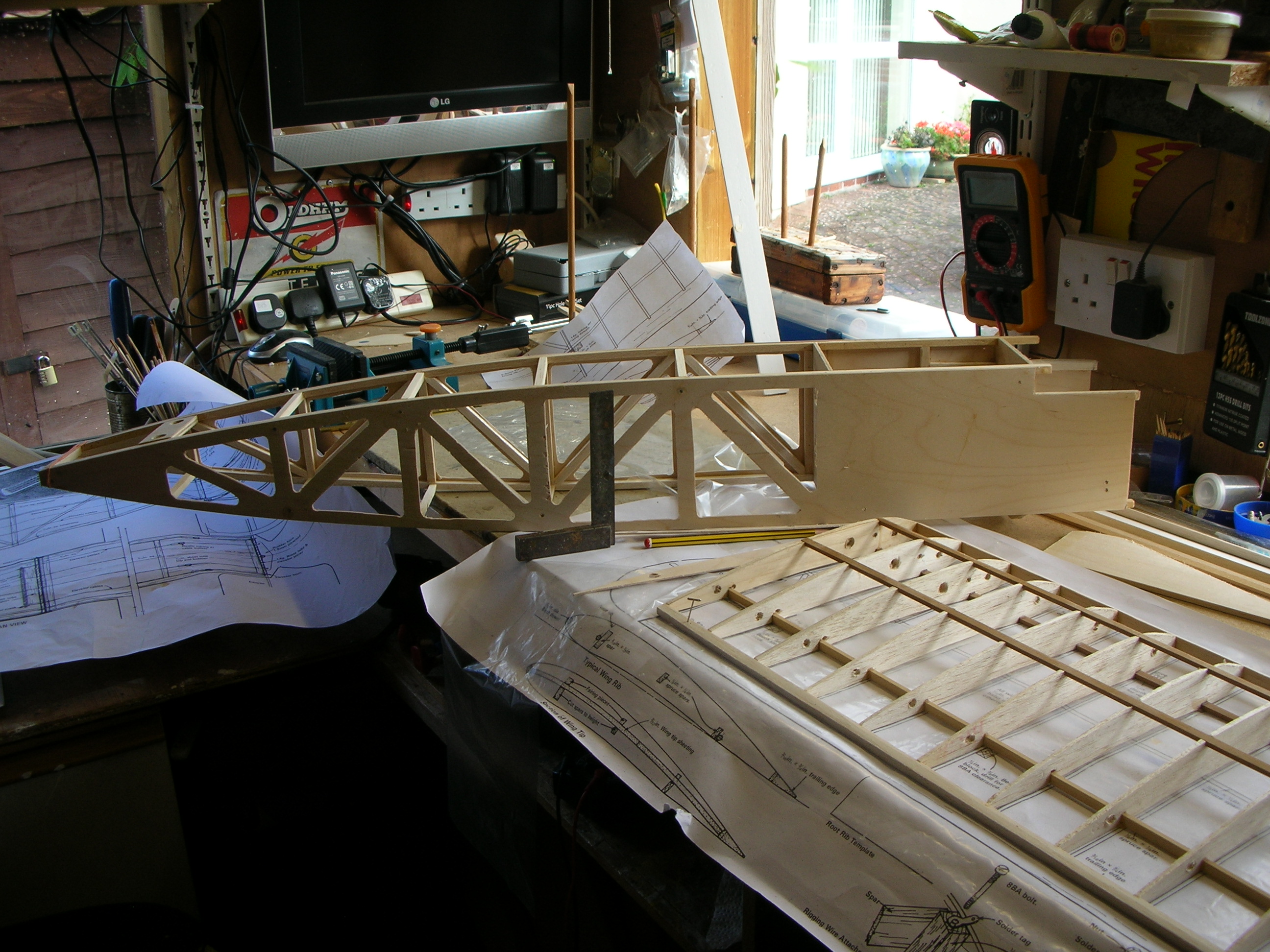
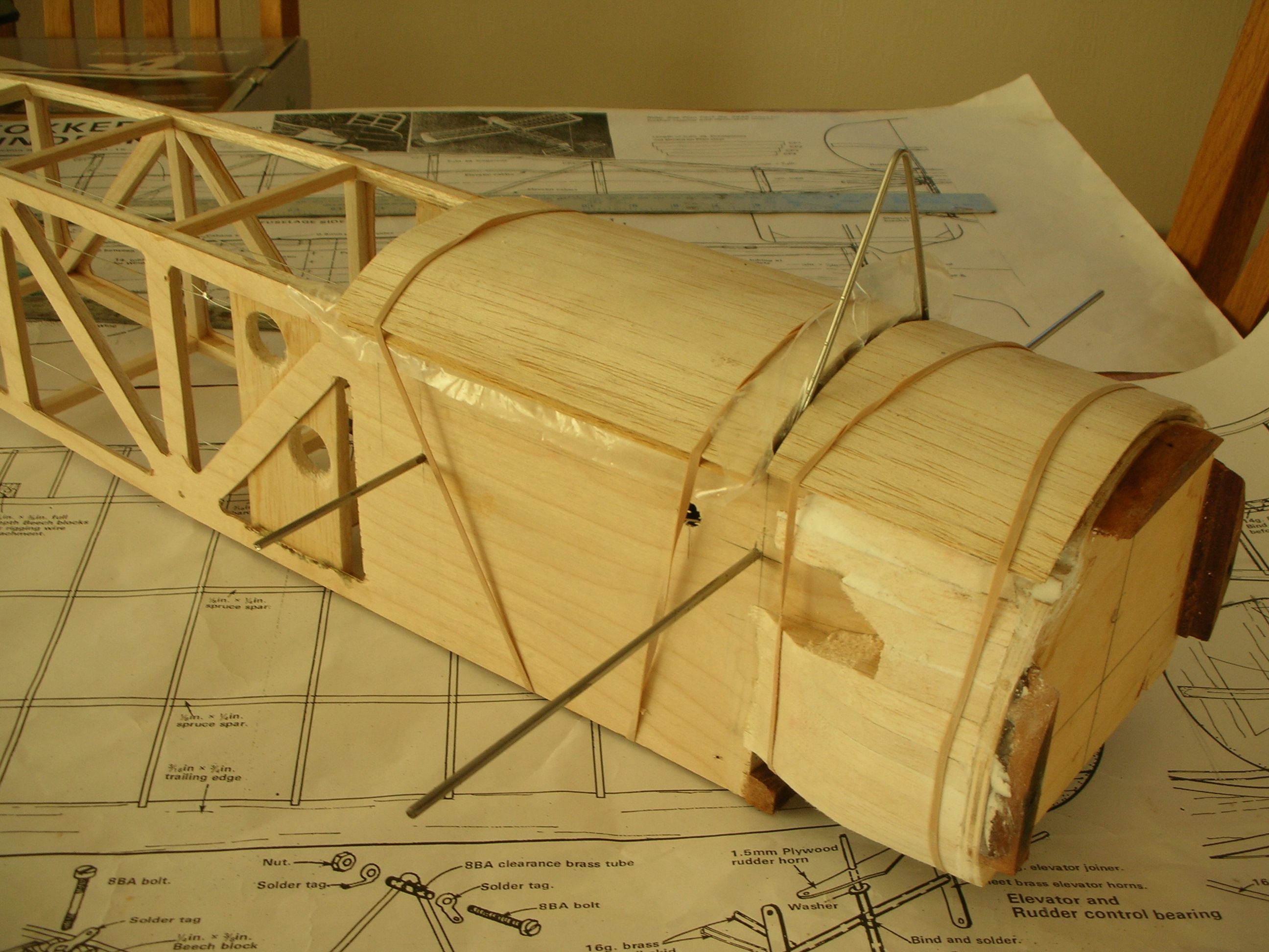
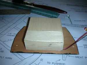
Photo 1. Fuselage framing with plywood sides glued and spacers installed.
Photo 1. Shows the part constructed fuselage with the 1/8 plywood sides glued in place, balsa spacers and ¼ ply tail skid mount.
On the bench, under the fuselage is a partly constructed wing. The DB design ribs with centre spars looked fiendishly difficult to make, so I made the choice of building with external spars as shown in the photograph.
Ribs were made using the sandwich method from 1/16th balsa sheet with1/8th plywood templates.
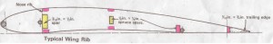
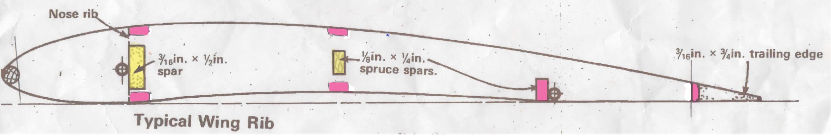
Photo 2. Wing rib template showing DB design and my alternatives.
The yellow is the DB design, the pink are my spars – all 1/8 x 1/4 spruce, I also added 1/16 vertical balsa webbing along the main spar, and a 1/4 balsa false trailing edge – I wasn’t going in for wing warping, just seemed altogether far too difficult and beyond my ingenuity or construction abilities.
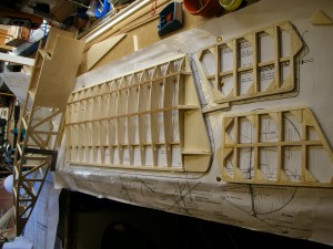
Photo3. Completed wings ready for covering.
9g metal gear servos inserted between 5th and 6th ribs, taking care to ensure opposite stroke of servo arms! The Brass wing joining tubes and locators were glued in using epoxy at this stage. The structures then sanded and finished with 280 and 400 wet/dry used dry – take care with the dust!
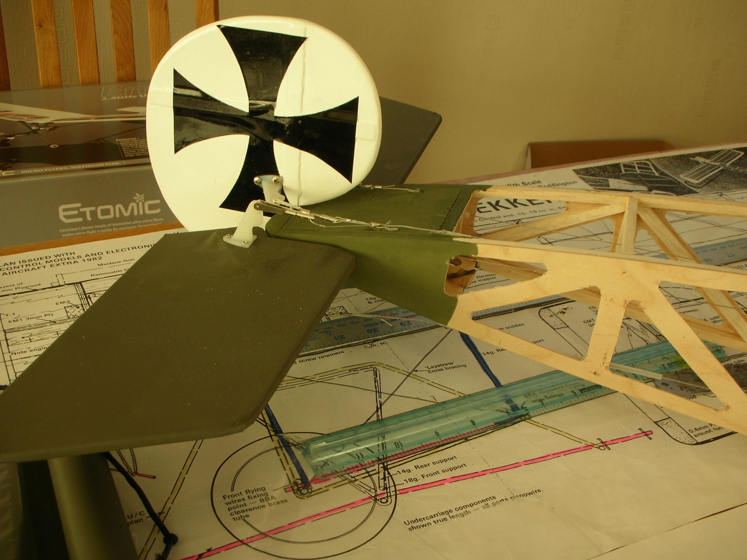
The rudder is 3/16th sheet balsa with cross grain inserts, and a vertical 16g piano wire hinge which slides downward into a brass tube which then also supports the fixing for the piano wire tail skid mounting. The elevator halves were made over the plan first, then the brass swivel tube was epoxied in with both halves held flat and inline together on the bench, the brass tube was cut after the epoxy was set thus ensuring both halves equal hinge fixing!
I chose standard size servos for the rudder and elevator – Futaba 148s – these were in the drawer! Besides, there’s loads of room! The rudder and elevator are both operated by closed loop, the tricky bit was fixing the full direction elevator operating unit and arranging the linkage to the servo.
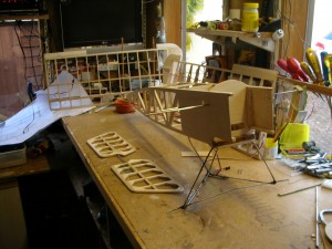
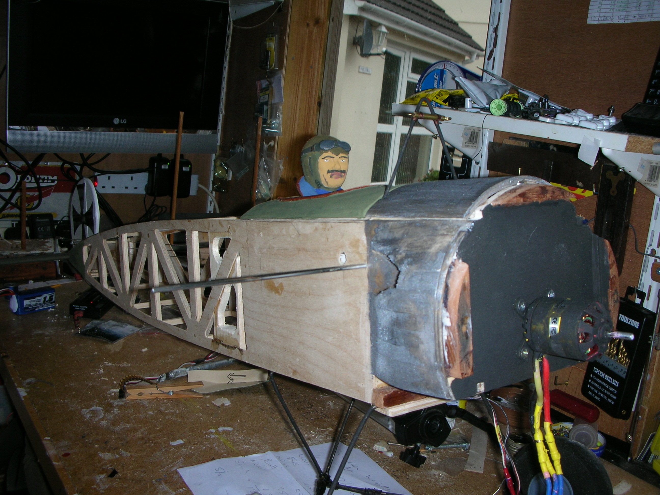
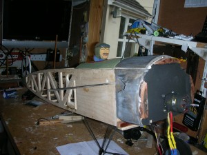
Photo 4. Fusealge before firewall fixing
Fokker Eindekker Build – Autumn/Winter 2014
Part 2
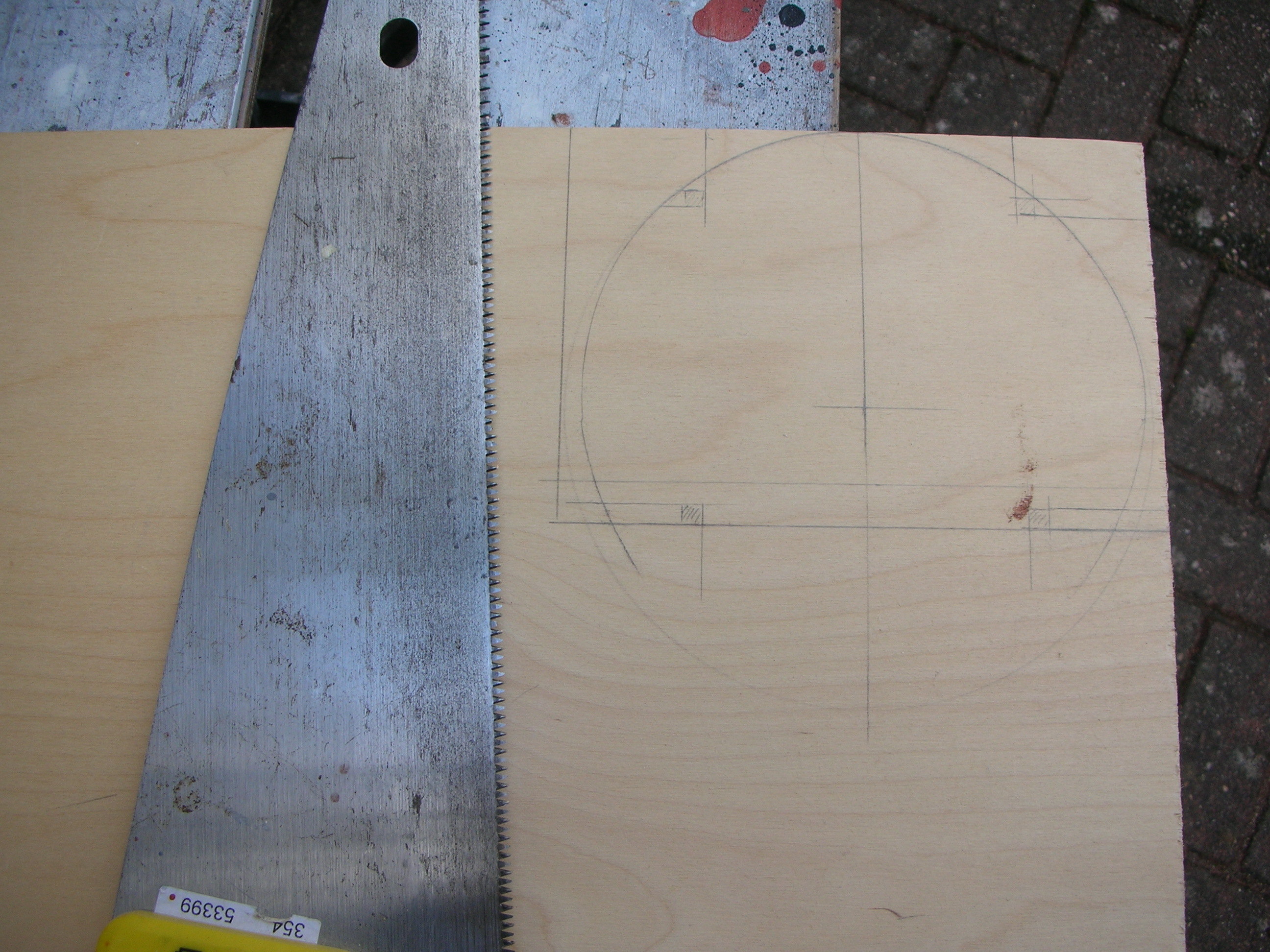
The firewall of ¼” ply was marked up from the drawing, and then cut out with the coping saw, glued directly to the leading edges of the plywood fuselage sides, and the joints reinforced with triangular fillets.
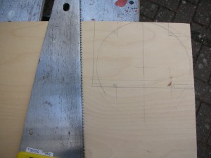
Photo 4. Firewall marked out ready for cutting
With the firewall in position, the hunt was now on for a suitably sized aluminium saucepan to cut the engine cowling from. There was no suitable utensil in the kitchen! So I made a tour of the charity shops. After a fruitless search on countless charity shops for an aluminium saucepan, the British Heart Foundation came up with a stainless steel one of the correct diameter. Steel would be more difficult to work, but have to deal with availability, besides, the extra few grams might save a bit on any future necessary ballasting!

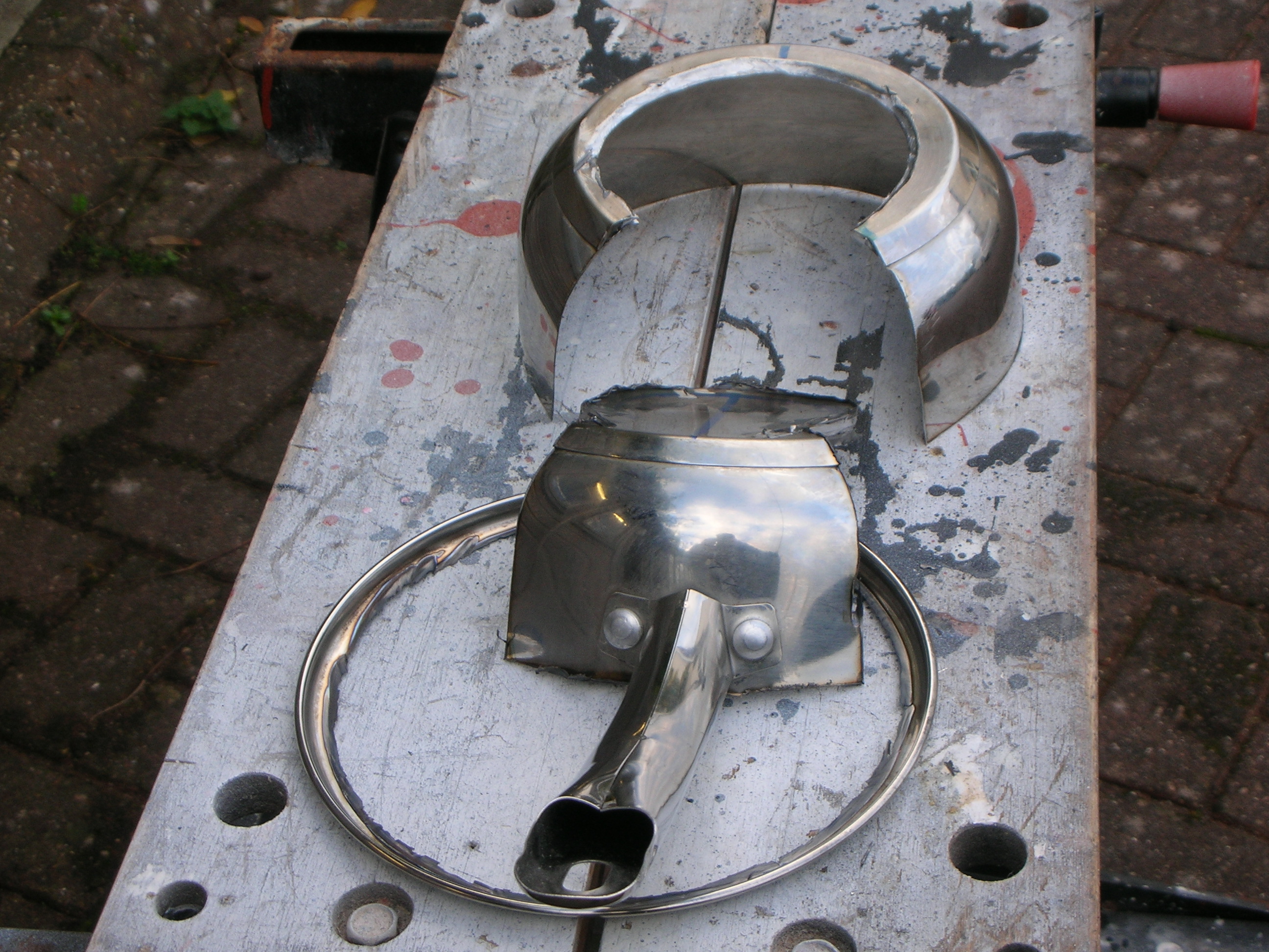
Photo 5. Cowling saucepan after cutting.
The disc cutter easily removed the rim of the saucepan, and with a bit of jiggling it cut out the shape as near as I could determine from photographs and drawings available on the various web sites. Then a bit of work with a sharp file, and the saucepan was looking a bit like a radial engine cowling!
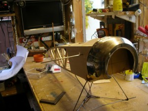
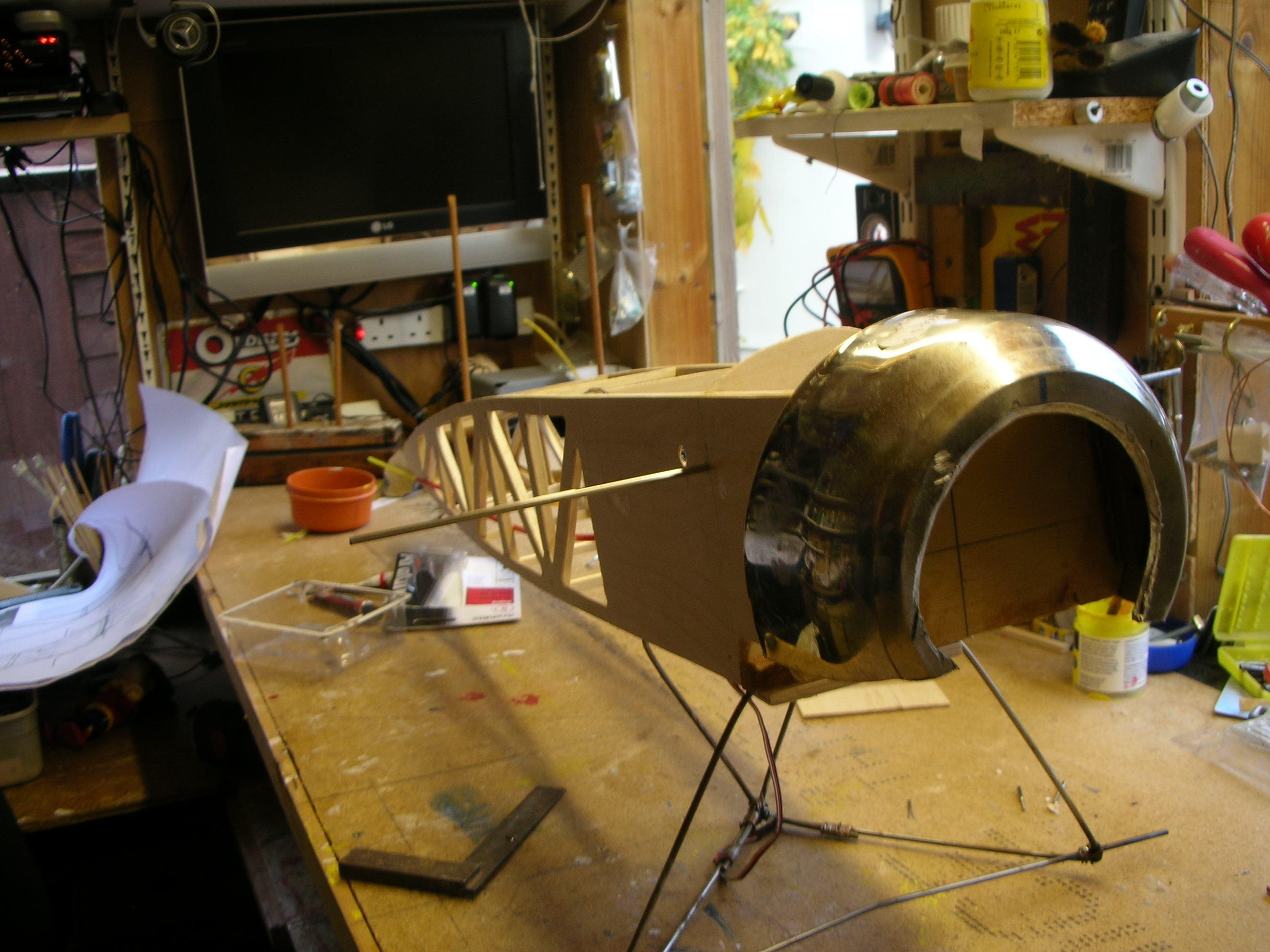
Photo 6. Trial fit of cowling
There is plenty of room for fitting the servos. As mentioned earlier, the tricky bit was mounting and fixing the full direction elevator operating unit and arranging the linkage to the elevator servo. Straight forward closed loop for the rudder using a 2” servo arm; just a bit tiresome pulling the operating wires taught whilst keeping all true and level.
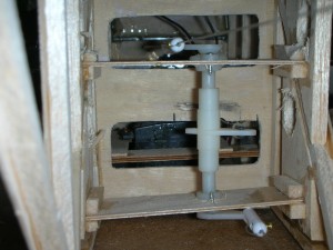
Photo 7. Inside view of the full direction operating arm
End of Part Two
Fokker Eindekker Build – Autumn/Winter 2014
Part 3
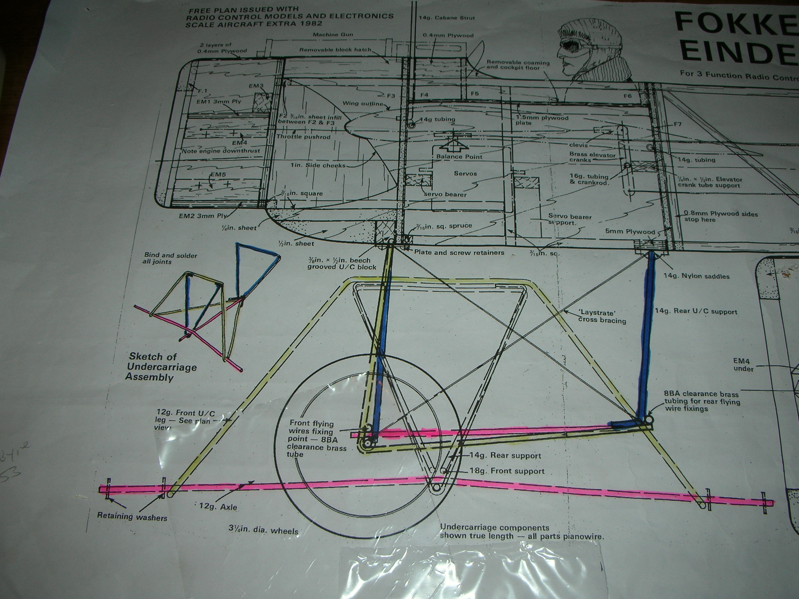
In photo 6 can be seen the undercarriage – not too well focussed! The undercarriage is made from 14 SWG piano wire bent up in the vice and shaped up with a lump hammer, then bound with copper wire – earth wire stripped out of 1.0 mm2 twin and earth (6242Y), and soldered with a plumbing blow torch and lots of flux!
The completed undercarriage is fixed to the fuselage with ply plates suitably grooved to hold the wire fore and aft, and screwed to plywood and solid supports glued into the bottom of the fuselage.
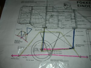
photo 8. Undercarriage coloured up for clarity.
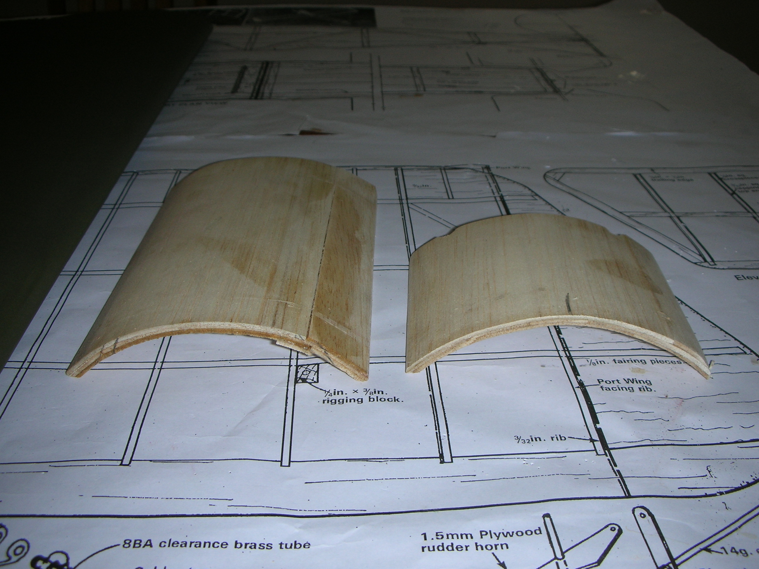
The curvy top pieces are 3 layers of 1/16th balsa wetted and glued together using PVA and shaped around a 2.5 litre paint tin. The foremost curvy hatch is for access to the ESC and sound unit, the hatch is held in place with magnets ,(the sound unit is on the shelf waiting, but might prove too heavy), on the other hand, if the 120gram loud speaker can be mounted right in the nose it will become a useful addition to the nose weight in order to achieve the required CofG.

Photo 9. Front hatch and cockpit cover after release from the paint tin mould!
To form the cockpit as a lift out unit allowing access to the servos below, a box was made from light balsa and the curved cockpit cover glued to the shaped top of the box. Both covers were then banded in place taking special care that the cockpit box and cockpit cover are not glued to the fuselage. The cockpit was cut out and fitted with a rubber tube coaming made from split 3/8th surgical rubber from my old bungee, glued in place with epoxy. The pilot is a bit ugly, and may benefit from a little more cosmetic makeup!

Photo 10. Cockpit cover and front hatch banded in place for final shaping.
The cockpit cover has a couple of coats of Humbrol matt Khaki (86), which is pretty close match to “Drab Olive” Solartex used to cover the elevator, wings and open frameworks, the rubber cockpit coaming is painted with Humbrol Brown (133), the firewall and motor presently have a coat of Japlac matt black, dummy engine to follow! And the forward hatch and engine cowlings have a priming coat of DIY silver modelling paint.
Forward hatch and cockpit in place, primer coat of silver; first coat black paint inside cowl – hardwood mounting blocks top and sides.
Photo 11. Cockpit cover and front hatch fitted and paintwork started.
End of Part Three
Part 4 Fokker Eindekker Build – Autumn/Winter 2014
There are always a myriad of detailed tasks to tackle as the final construction of a model is approached. Naturally, scale models come with far more bits requiring attention, for the Eindekker this included connecting and trialling of the sound system to determine performance, will it fit? And can it be a useful contribution to the ballast! A temporary hook up showed the unit to exceed expectations as far as the sound is concerned – it will fit easily, and ballast will be required! Disconnect and put to one side for later installation!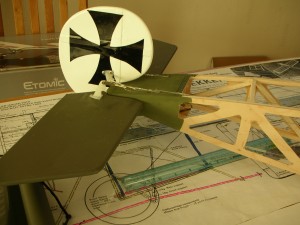
Photo 12. Elevator halves covered, assembled, and closed loop control installed
Much of the covering was carried out on the ironing board using a Prolux covering iron. Much easier to handle the components using the ironing board – accessible equally from each side – than on the workbench; further, a large table is required to lay out and mark the covering material for cutting – fortunately the dining room with large dining table for laying out the Solartex is available, and the room is comfortably large to be able to work around the table, and to have the ironing board accessible too!
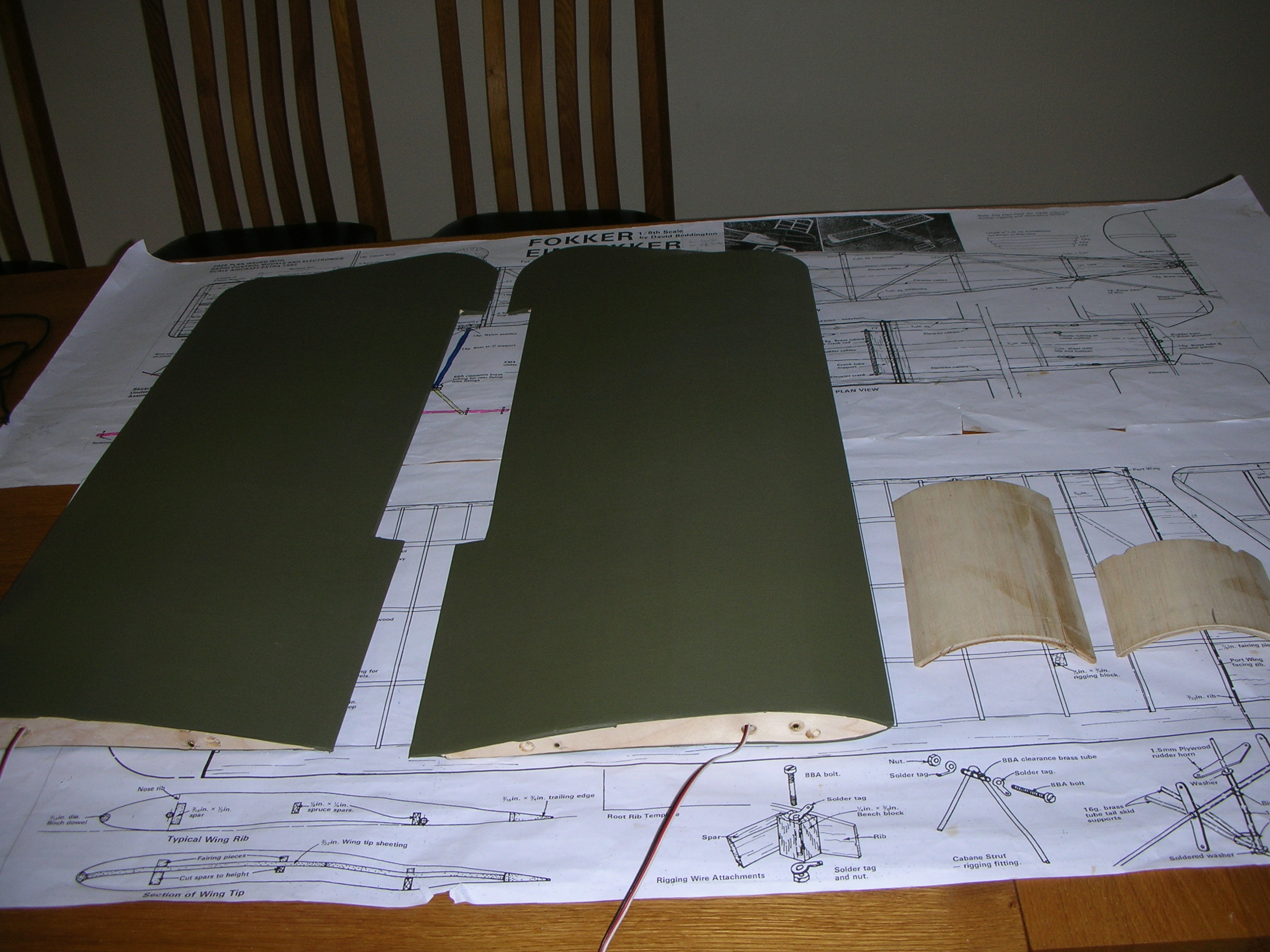
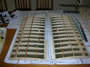 Photo 13. Underside of wings covered
The elevator halves were covered first renewing familiarity of working with the Solartex following the summer ‘love in’ with foamies! Emboldened by success with the elevator halves the underside of the under cambered wings were tackled next, essential that the material is properly adhered to the under cambered ribs and the underside of the spars – carefully working along the main spar and then outward from the spar along the ribs to the rearward spar, and finally along the outer ends of the ribs to the leading and trailing edges. Just like measuring and cutting – “measure twice, cut once”, but here, “check, check and check again for good adhesion” before attempting to shrink and tighten the Solartex!
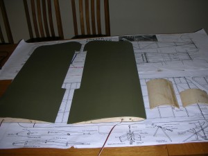
Photo 14. Wings covered – ailerons to be fitted
End of Part Four
Part 5 Fokker Eindekker Build – Autumn/Winter 2014
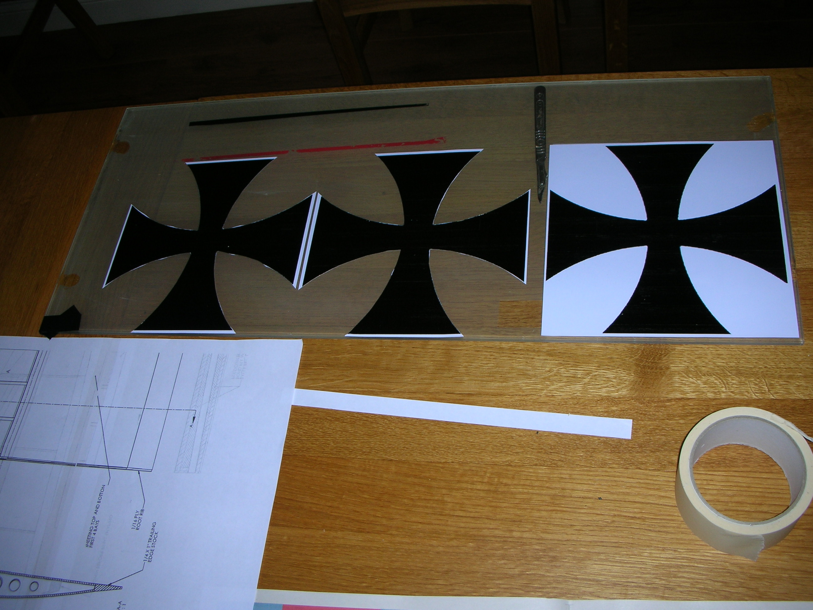
Decals are by courtesy of Ian, Photo Shopping the Maltese crosses, these were then printed onto self adhesive vinyl sheets and laid over the surfaces of the wings. However, the adhesive on the vinyl proved insufficient and the decals would not stick properly to the Solartex! Bitter experience has shown that using masking tape and brush painting on Solartex can suffer from seepage of the paint underneath the edges of the masking tape resulting in scruffy and ragged edges. Spaying seemed the alternative. The decals were removed and stuck onto glass sheet for later use.

Photo 15. Vinyl decals in safe keeping on glass sheet
The areas of the white background were masked off and sprayed with matt white. The Maltese crosses were shaped by cutting the white background from each corner of the decals, fixing these onto the spayed white squares, and the remaining spaces of the crosses sprayed matt black, finally the decal corners and the maskings were all removed, and some minor touching up around my clumsy cutting edges!
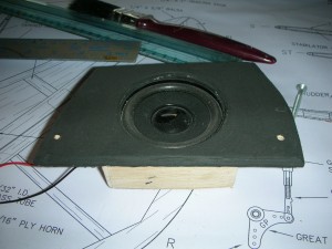
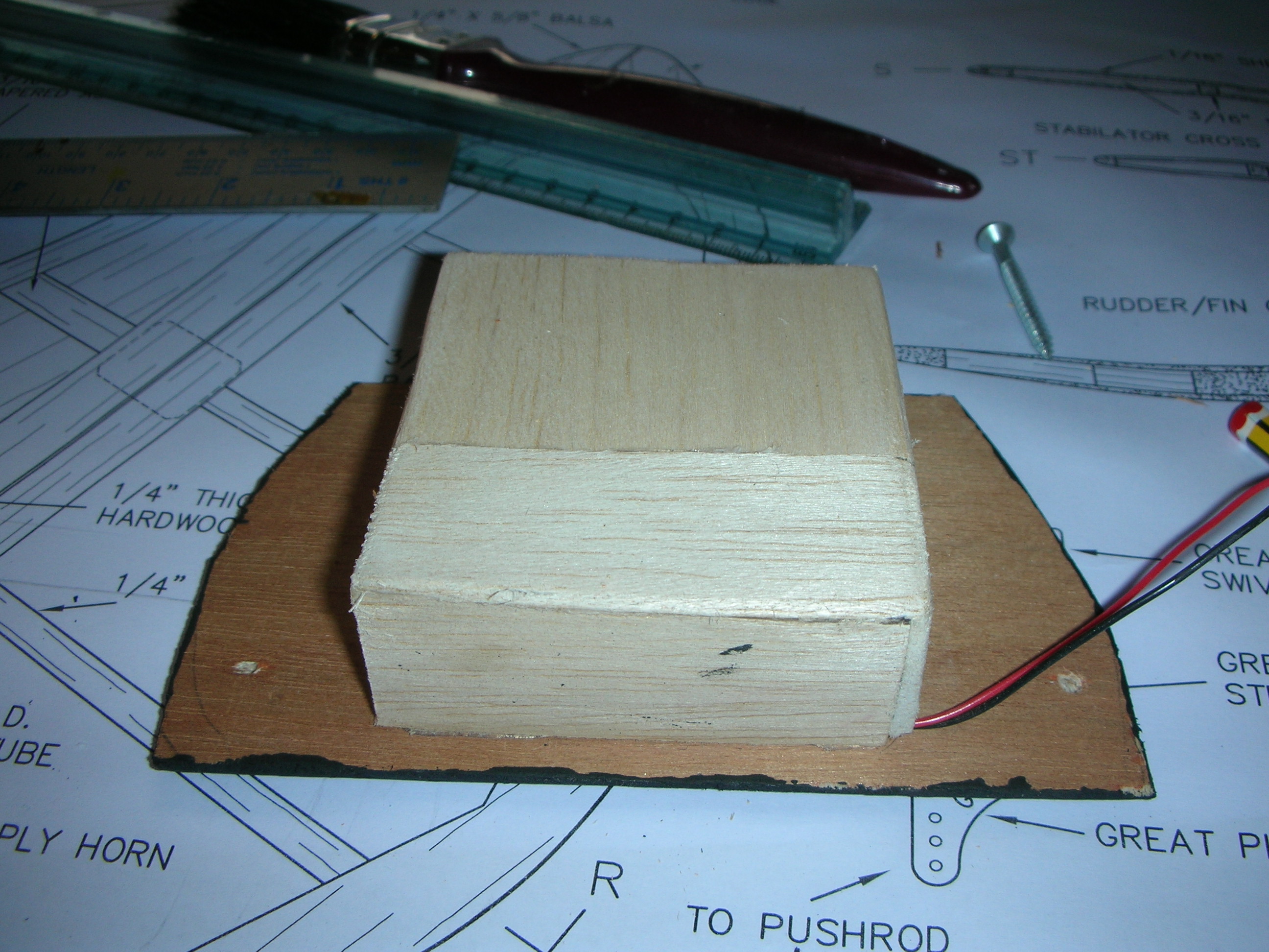
Photos 16 & 17 showing the loudspeaker mounting and sound insulating box
The sound system electronics was fitted underneath adjacent to the servos, and the loudspeaker mounted facing down in the bottom of the front hatch built into a balsa box, the spaces around the back of the loudspeaker inside the box filled with foam rubber to dampen unwanted vibration in the airframe, the loudspeaker in its mounting box glued to the underside of the forward lower hatch.
End of part 5
Part 6 Balancing – Getting the C of G right!
The model was assembled complete with batteries, cockpit and forward hatch cover: resting the model on the twin dowels of the traditional balancer with the dowels set 70mm from the leading edges as prescribed on the plan proved more difficult than expected because the undercarriage was fouling the dowels. Another method was called for! Two small holes were drilled in the top rails of the cockpit coaming at the C of G, and a slender wire threaded through the holes, using this wire the entire airframe was suspended from the dining room light fitting!
Adding lead weights to the nose quickly built up to an alarming 2.3kg, this required 5 layers of 7lb gauge lead roofing sheet cut into H shapes to fit around the motor and screwed to the front face of the firewall. This achieved the correct balance, but at what a weight penalty!
The engine cowl is almost 2 inches (50mm) in length, if the ballast could be moved forward to the front of the cowl the actual weight would be reduced because the turning moment around the C of G would 2” (50mm) longer, the reduction in weight would not be much, but any reduction would be worth having!
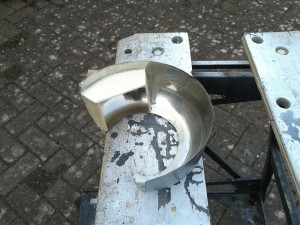
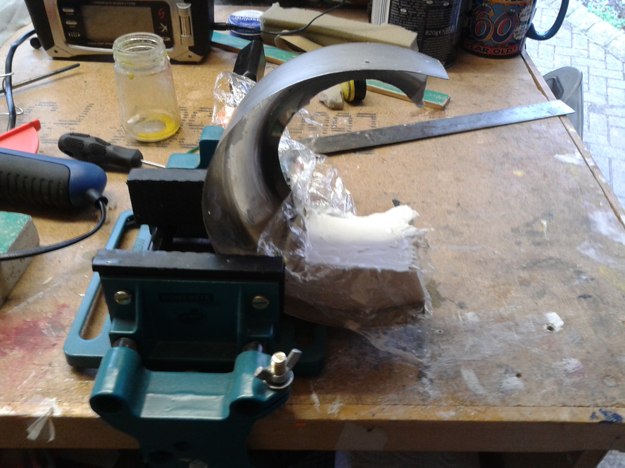
Photo 18 – making the balsa mould inside the cowl
A balsa mould was glued inside the cowl and decorating filler poured into the cling film protected mould. When hard the filler cast was removed and cleaned, then wrapped tight with Clingfilm and used as a die set inside a weak sand and cement mortar mix to give the lead weight ingots shaped as the inside of the cowl.
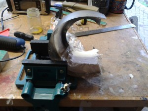
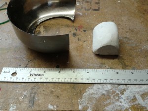
Photo 19 and 20 – Filler poured into the mould and filler die ready to fit into mortar for mould
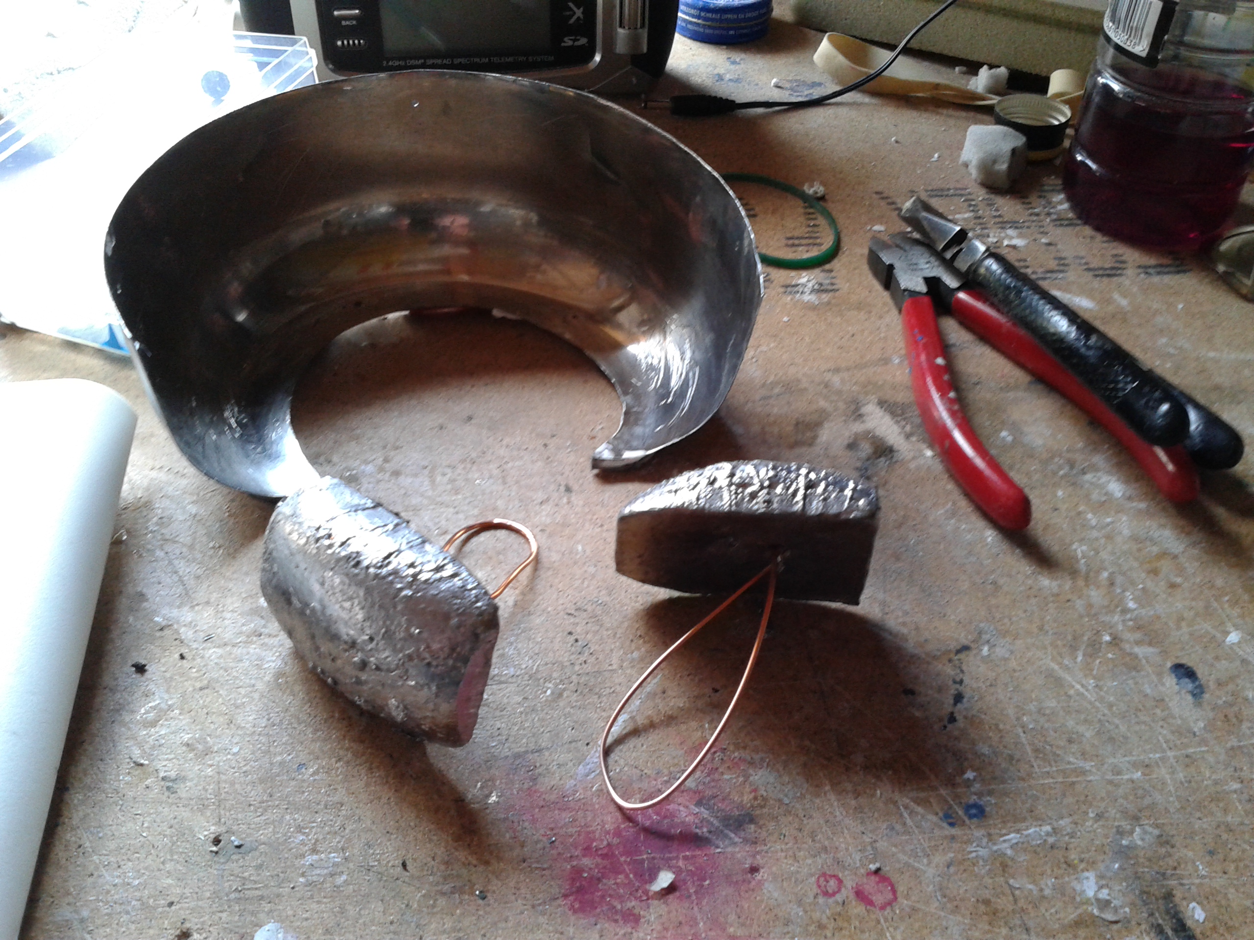
Two lead weight ingots made as described above, together with 100 grams of lead sheet all glued inside the front of the cowl now balanced the model with an overall saving of almost 550 grams of ballast, a reduction well worth having!
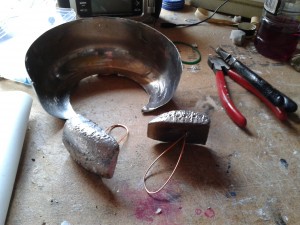
Photo 21 – Lead weights with copper wire handling loops
End of Part 6